


Modern construction machinery is now highly networked systems. Sensors, control units and safety modules communicate with each other constantly – and this happens via the so-called CAN bus .
The CAN bus is essentially the nervous system of every modern machine. Understanding how it works allows for faster troubleshooting, prevention of failures, and safer machine operation.
CAN bus explained simply
CAN stands for Controller Area Network . It was developed by Bosch to connect multiple control units using only two wires – CAN High and CAN Low . These twisted copper cables transmit digital signals in real time that all components understand. This allows engine control units, hydraulics, tilt sensors, and joysticks to communicate with each other without delay.
- Transmission rate: 250–500 kbit/s
- Maximum cable length: approx. 40 m
- Participants per network: up to 254 control units
- Voltage difference: approx. 2–4 V between CAN H and CAN L
From J1587 to J1939 – the development
Previously, many machines used manufacturer-specific systems (J1587, J1708). These were slow, inaccurate, and required manual querying. Today, the international standard SAE J1939, with its diagnostic extension J1939-73 , dominates. It ensures that the engine, hydraulics, and control system speak the same language – regardless of the manufacturer.
- Until 2010: J1587/J1708 – reactive fault diagnosis, hardly standardized
- From 2013: J1939-73 – active fault communication (DM1–DM3)
- From 2024: J1939-14 – new generation with 500 kbit/s transmission rate
This is how the diagnosis according to J1939-73 works.
The system works with so-called Diagnostic Messages (DM) . As soon as a sensor or control unit detects a deviation, it automatically sends a message via the bus – entirely without the need for workshop equipment.
- DM1: Active errors, transmitted every second
- DM2: Inactive errors, already fixed
- DM3: Live sensor data without errors
This gives the technician all relevant information in real time: what happened, how serious the fault is, and how often it has already occurred.
Structure of the error codes
Every mistake consists of two parts:
- SPN (Suspect Parameter Number): describes the affected component
- FMI (Failure Mode Identifier): describes the type of error
Example:
SPN 5261 + FMI 1 = Pressure sensor lifting cylinder – signal too low
This allows a technician to immediately distinguish whether it is an electrical fault, a hydraulic loss, or a communication problem.
FMI meanings at a glance
| FMI | Error type | Typical meaning |
|---|---|---|
| 0 | Data incomplete | Sensor not responding |
| 1 | Signal too low | Voltage or pressure below setpoint |
| 2 | Signal too high | Overvoltage, short circuit |
| 3 | Unexpected anomaly | Electrical interference pulse |
| 4 | Frequency/pulse width faulty | Sensor delivers unstable signal |
| 5 | CAN message rate too low | Connection was lost |
| 6 | CAN message rate too high | Signal overload, communication errors |
| 7 | Mechanically jammed | Potentiometer blocked |
| 9 | Message missing | Cable break or plug fault |
| 31 | Unknown | Errors are present but not assigned. |
Which manufacturers use which system
| Manufacturer | System type | Description |
|---|---|---|
| Magni | J1939-73 | Full CAN integration with Deutz engine, DM1 every 1 second |
| Merlo | Hybrid (MD-Coder + J1939) | Engine = Standard J1939, Body = proprietary |
| Manitou | Proprietary Hex Code | Partially J1939 compatible, many special codes |
| JLG | Proprietary CAN system | Unit Group Module (UGM), partially J1939-like |
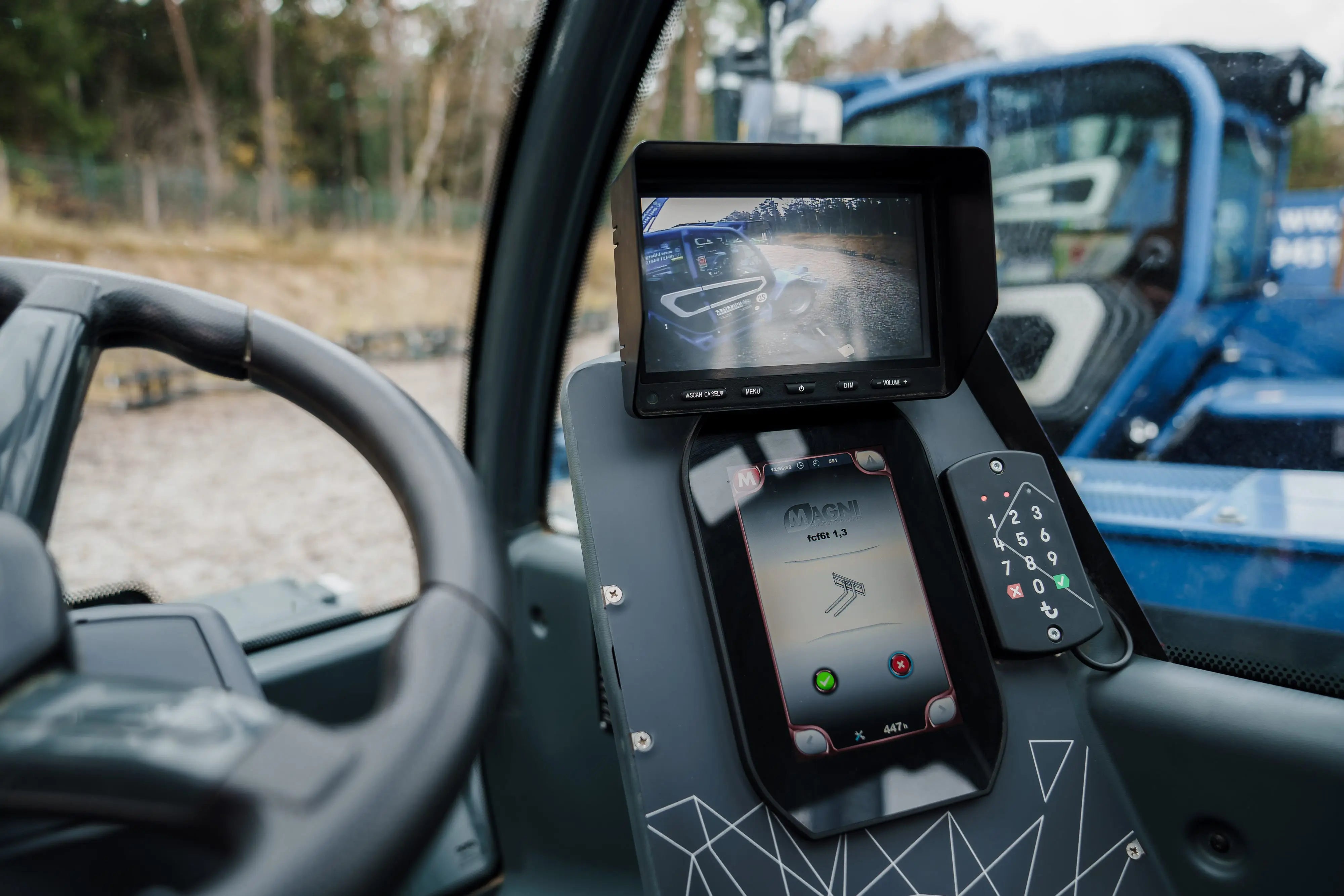
| genius | CAN variants | Model-dependent, error message displayed on screen |
| CAT | Proprietary | Compatible with CAT Service Advisor only |
| Deutz | J1939-73 | Standardized engine control (SPN 1000-1500) |
| Agricultural machinery (Claas, Fendt) | ISOBUS (ISO 11783) | Extended J1939 standard for agricultural machinery |
Top 6 CAN errors in practice
These faults occur most frequently in workshops and rental fleets. The table shows typical symptoms, measured values, and practical advice.
| Mistake | SPN / FMI | Typical voltage (V) | Caused | measure |
|---|---|---|---|---|
| Joystick signal faulty | 5300 / 3 | 0 V (instead of 0.5–4.5) | Broken cable or misaligned potentiometer | Recalibrate or replace joystick |
| Pressure sensor lift cylinder A/B difference | 5261 / 1 | 1.2 V (instead of 2.5) | Hydraulic leak or corroded connector | Visual inspection + contact spray, sensor measurement |
| CAN bus timeout | 5400 / 9 | CAN L: 0 V – CAN H: 4.8 V | Termination resistor defective or cable broken | Check resistance (60 Ω between H and L) |
| Tilt sensor timeout | 5280 / 0 | No communication | Moisture or frost in the sensor | Dry/replace sensor |
| Accelerator pedal voltage too low | 1015 / 1 | 1 V (instead of 5 V) | Defective potentiometer or oxidized connector | Measure voltage + replace part |
| Hydraulic overload warning | 5321 / 3 | Signal 0 V → Peak value > 12 V | Overvoltage caused by hydraulic surge | Check system pressure / Calibrate valve |
Seasonal influences
winter
- Battery voltage below 24 V: leads to CAN errors and starting problems.
- Hydraulic oil too viscous: Pressure sensors report "signal too low".
- Frozen tilt sensors: typical error SPN 5280 / FMI 0.
Summer
- Moisture and corrosion: frequent SPN 5400 / FMI 9 messages.
- UV aging: brittle cable insulation and increasing contact problems.
Operator responsibilities and legal requirements
According to DGUV 308-009, operators must understand error messages and react correctly. Clearing errors is permitted only to authorized technicians. Error messages must not be ignored – even if the machine is still functioning.
- Identify errors and document them in the inspection log.
- Shut down the machine in case of critical warnings.
- Inform the landlord or repair shop immediately.
- No manipulation or bypassing of sensors
Overview of diagnostic tools
- MyMagni Portal: Cloud-based fault monitoring including GPS and maintenance history
- MerloDiag: PC software for MD-coder systems (USB dongle)
- JLG Analyzer: Handheld device for direct CAN querying
- MultiECUScan: Universal diagnostic tool for J1939 and OBD protocols
Future of the CAN bus
The trend is moving towards higher speeds and cloud-based diagnostics. With J1939-14 and CAN-FD, data throughput is doubled, enabling more precise fault analysis and predictive maintenance.
- J1939-14: 500 kbit/s standard from 2025 (compatible with older systems)
- CAN-FD: up to 5 Mbit/s, more data per message (64 bytes instead of 8)
- Wireless Diagnostics: Fault analysis via LTE/5G
- AI-powered error prediction: Analysis of historical DM1 data
Conclusion
The CAN bus is the central control unit of modern construction machinery. Understanding its structure and error logic according to J1939-73 saves time, prevents downtime, and increases workplace safety.
Whether Magni, Merlo or JLG – they all work according to a similar principle: detect errors early, react appropriately and rectify them systematically. This is how complex electronics become a reliable everyday partner on the construction site.


Share:
Magni Diagnostic Guide: How to correctly interpret error messages
Become a forklift driver: safely, trained and responsibly
Our editorial quality standards
The subject content on biberger.de are editorially created, reviewed, and continuously updated. The basis is our daily work with aerial platforms, telehandlers, and industrial trucks – in rental, sales, operational planning, and technical support.
Each article draws on real-world experience and is editorially reviewed for clarity, accuracy, and practical relevance according to expert criteria. Technical statements are regularly compared against current industry standards and best practices.
The aim of our publications is to make reliable specialist knowledge accessible and to offer guidance to users, decision-makers and industry partners. BIBERGER sees itself as an independent information platform for safe, economical and modern height access technology – well-founded, comprehensible and free from advertising influence.