


Oscillating axles are a crucial component of modern work platforms , telehandlers , and off-road vehicles. They ensure that machines remain stable and can operate safely even on uneven surfaces . In this guide, we explain the technology, safety requirements, maintenance, troubleshooting, and future trends – in a practical, understandable way, and with real-life examples from everyday use.
Basics – what is a swing axle?
A swing axle compensates for uneven ground by allowing the wheels to move independently of each other. While with a rigid axle, both wheels are firmly connected, a swing axle allows one wheel to descend or ascend without the frame tipping. This keeps the machine stable even when the ground gives way.

The swing axle compensates for uneven ground and ensures that all wheels always maintain contact with the ground.
Advantages at a glance
- Even ground contact on uneven terrain
- Less frame stress and material wear
- Better traction and lower risk of lateral tilt
- Greater operational safety on construction sites
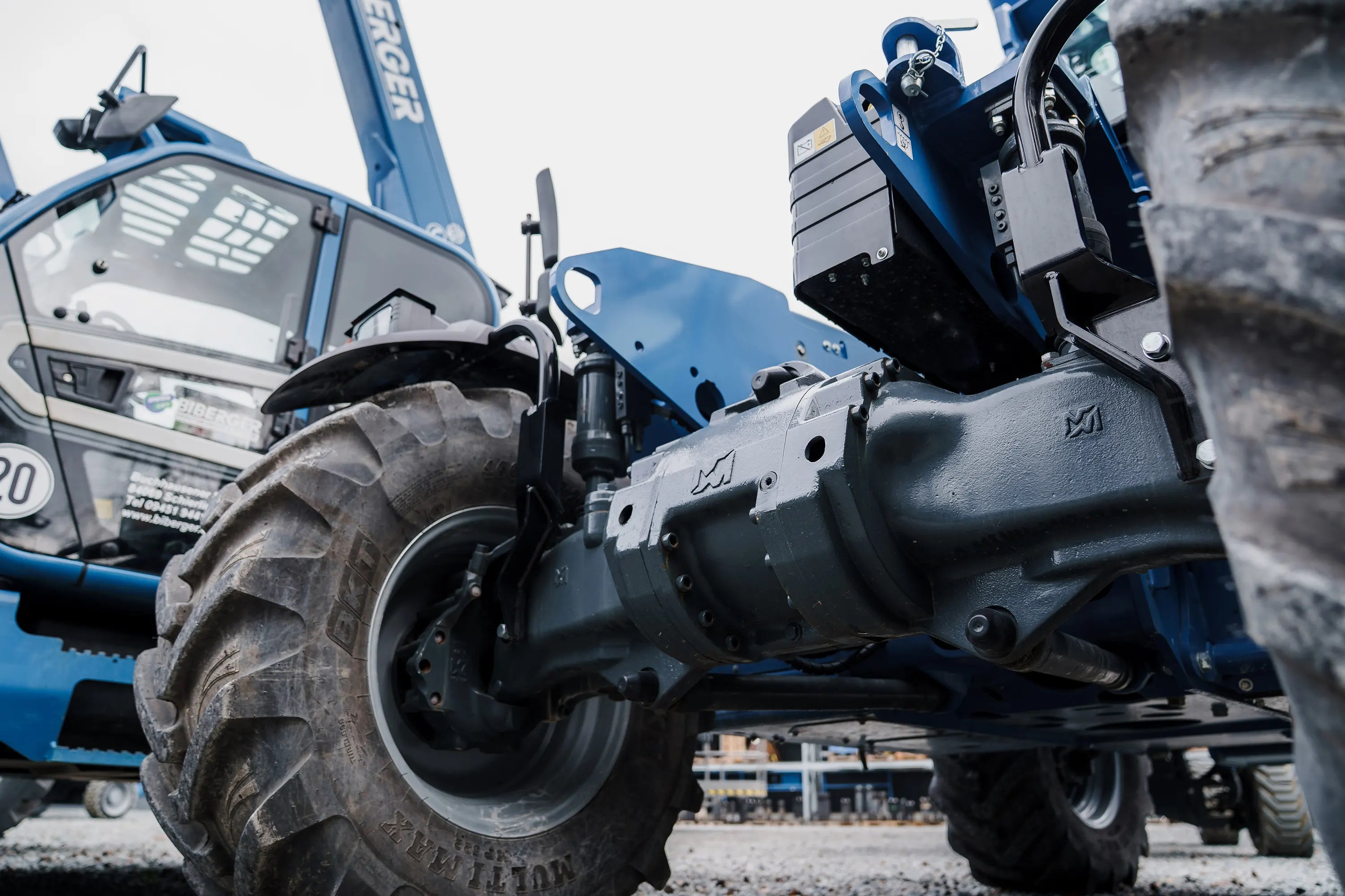
Structure and functionality
The oscillating axle is connected to the main frame via a central joint or pivot point. Two hydraulic cylinders allow controlled oscillation, while valves lock the system during work operations. During travel, the axle can move freely; when the platform is raised, a solenoid valve automatically blocks the oscillation.
Hydraulic control and locking
The hydraulics of the pendulum axle operate with two different pressure ranges: The cylinders' operating pressure is 300–600 bar, while the opening pressure of the locking valve is only 12 ± 2 bar. This low locking pressure keeps the valve closed until the axle is deliberately unlocked. Check valves maintain pressure even in the event of a line break.
Technical specifications
- Compensation travel: 10–45 cm
- Opening pressure shut-off valve: 12 ± 2 bar
- Max. flow rate: 20–30 l/min
- Cylinder pressure range: up to 600 bar
Safety aspects and stability
The pendulum axle directly impacts stability. An unlocked or defective axle can cause dangerous tilt changes. Even small angular deviations significantly increase the tipping moment, especially with large booms.
Technical background
Stability is calculated according to EN 280. The ratio of the static moment to the overturning moment must be at least 1.25:
S S = Standmoment / Kippmoment ≥ 1,25
If this value drops, there is a risk of instability – especially on uneven floors or with asymmetrical basket loads.
Critical tilt angles
- Lateral inclination: max. 3–5°
- Longitudinal inclination: up to 8°
- With extended basket: max. 2–3° sideways
Example calculation – critical scenario
 Example extreme situation (Genie S-65 XC):
 Dead weight: 8,000 kg
 Basket load capacity: 450 kg
 Outreach: 18 m
 Track width: 2.5 m

 Tipping moment = 450 kg × 18 m = 8,100 kgm
 Static moment = 8,000 kg × 1.25 m = 10,000 kgm
 Safety factor = 10,000 / 8,100 = 1.23 → critical limit
This calculation shows a deliberately aggravated situation. In practice, the safety factor for most machines (e.g., Genie S-65 XC) is significantly higher—typically between 1.4 and 1.6. However, it illustrates how quickly stability can be lost if the oscillating axle is not locked.
Recommended measures
- Before each lift: check the lock
- Calibrate inclination sensors regularly
- Keep warning systems active
- Conduct operator training with inclined position scenarios
Manufacturers and systems
| Manufacturer | Models | System type |
|---|---|---|
| genius | S-45 XC , S-65 XC, SX-180 | Active hydraulic pendulum axle |
| Manitou | MH 25-4, M 30-4 , M 50-4 | Mechanically swinging with automatic locking |
| JCB | Industry Plus / Pro | Standard swing axle |
| Dinolift | Dino 210XT II | Hydraulic with sensor control |
Genie scissor lifts with pendulum axle – overview
Genie offers optional oscillating axles on scissor lifts – they are not standard on all models.
Rough terrain scissor lifts (GS-RT series)
| Model | drive | Swing axle | Working height |
|---|---|---|---|
| GS-2669 RT | Diesel | Optional | 10.0 m |
| GS-3369 RT | Diesel | Optional | 11.0 m |
| GS-4390 RT | Diesel | Optional | 13.4 m |
| GS-5390 RT | Diesel | Optional | 13.4 m |
Hybrid models (GS-BE series)
| Model | drive | Swing axle | Working height |
|---|---|---|---|
| GS-2669 BE | Hybrid | Optional | 9.7 m |
| GS-3369 BE | Hybrid | Optional | 11.0 m |
| GS-4069 BE | Hybrid | Optional / Standard | 12.2 m |
Electric models (GS-DC series)
| Model | drive | Swing axle | Working height |
|---|---|---|---|
| GS-2669 DC | Electrical | Active swing axle as standard | 9.7 m |
Distinction – RT vs. DC vs. BE
| Row | Meaning | Swing axle | Typical use |
|---|---|---|---|
| RT | Rough Terrain (Diesel) | Optional | Outdoor construction sites |
| DC | Diesel / Electric (Hybrid) | Often standard | Flexible indoor / outdoor |
| BE | Bi Energy (New Hybrid Series) | Optional / Standard | Modern and environmentally friendly |
Important: Swing axle is optional, not standard
That means:
- Swing axle can be ordered
- Is not automatically included
Small scissor lifts such as the GS-1530 / GS-1930 / GS-2032 do NOT have a swing axle.
economy
Oscillating axles slightly increase the initial cost, but significantly reduce downtime and maintenance costs. Their use quickly pays for itself, especially in the rental business.
Cost overview
- Cylinder repair: €800–€2,000
- Pipeline repair: €500–€1,500
- Complete axle: €8,000–15,000
Error diagnosis and troubleshooting
Oscillating axle faults often only become apparent under load. Structured diagnostics prevent unnecessary downtime.
Error diagnosis table
| symptom | Caused | Test step | Solution |
|---|---|---|---|
| Asymmetric cylinder position | Valve stuck / uneven pressure distribution | Measure pressure left / right | Clean or calibrate the valve block |
| Delayed closure | Leak or worn solenoid valve | Observe pressure curve when locking | Replace valve |
| Axle remains locked during driving | Valve blocked in closed position | Check solenoid voltage | Replace coil |
| Axle warning light flashing | Sensor defect / CAN error | Check connector, read error memory | Replace sensor |
| Oil stains under machine | Hairline crack or porous pipe | Pressure test (150 bar) | Replace cable |
Check print and lock function
The opening pressure of the shut-off valve should be 12 ± 2 bar. Deviations indicate valve wear. To test the locking function, activate the lock and observe whether the pendulum axle remains stable—no visible movement or change in inclination. Modern machines also indicate the locking status via sensors on the display.
Leakage current
Leakage flows should not exceed the manufacturer's specifications. A locked axle must not drop measurably. Values above 1 l/min require inspection or replacement of the valve.
Maintenance and testing
Daily check
- Visual inspection for oil leaks and cracks
- Test locking function
- Check warning lights
- Compare ground clearance
Checklist for visual and functional testing
Annual UVV inspection
- Check valve and cylinder function
- Pressure test and sensor check
- Check cables for chafing
- Document results in the UVV protocol
Differences between axle types
| System type | Features | Advantages | Disadvantages |
|---|---|---|---|
| Rigid axle | Fixed connection | Simple, robust | No ground adaptation |
| Single-joint swing axle | Central pivot point | Light, compact | Limited compensation path |
| Two-joint swing axle | Two pivot points | High stability | More complex hydraulics |
| Adaptive swing axle | Sensor and software control | Automatic adjustment | More expensive, more maintenance-intensive |
Measurement and testing in practice
Static balance test
Position the machine on a 10° ramp and measure the wheel height difference. Target value: 10–45 cm. Deviation > 10% → Inspection required.
Function and valve testing
Static function test: Lift the machine, activate the lock, check whether the axle no longer oscillates (visually or via tilt sensor).
Valve check: Connect a pressure gauge to the test port – the opening pressure should be 12 ± 2 bar. Deviations of more than 15% require adjustment or replacement.
Logging
All tests must be documented in the accident prevention report – including the date, inspector, pressure values, and any deviations. This is the only way to ensure operational safety.
History and development
The swing axle originated in automobile construction in the 1930s (e.g., the Auto Union Type A, the Mercedes 190 SL). Starting in the 1980s, construction and lifting technology adopted the principle – initially mechanically, later hydraulically with shut-off valves. Today, adaptive systems with electronic control and sensors dominate.
Future and trends
Adaptive pendulum axles automatically adjust to the ground. Sensors measure inclination and load distribution in real time and adjust the hydraulic pressure accordingly. New materials such as aluminum and fiber composites reduce weight and energy consumption – an important factor for electric platforms.
Standards and regulations
- EN 280: Safety requirements for mobile elevating work platforms
- ISO 3691-4: Off-road industrial trucks
- DGUV 208-043: Working on shelving systems
- TRBS 2121: Technical rules for operational safety
Training and operator qualification
BIBERGER conducts training courses according to the SYSTEM CARD standard – a recognized qualification according to DGUV 308-008. The SYSTEM CARD is equivalent to IPAF certification and authorizes the safe operation of all types of work platforms.
During the one-day training, participants learn how to correctly use pendulum axles, perform safety checks, and identify typical errors. Upon successful completion, they receive a SYSTEM CARD, which is valid for five years and recognized throughout Europe.
Training content according to DGUV 308-008
- Structure and function of the pendulum axle
- Manual vs. automatic locking
- Functional test before starting work
- Recognizing error messages and warning signals
- Behavior in case of pressure loss or pipe breakage
Practical example – accident analysis
A documented case shows that an articulated platform tipped over at a working height of 12 meters because the pendulum axle wasn't locked. Today, automatic shut-off valves and warning systems reliably prevent such situations.
Glossary of important technical terms
- Swing axle: axle with vertical compensation between wheels
- Lock valve: Hydraulic valve that blocks the pendulum movement
- Check valve: Valve to maintain pressure in case of line break
- UVV inspection: Annual safety inspection according to DGUV V3
- Tilt sensor: Sensor for monitoring machine stability
Conclusion
Oscillating axles are more than just a technical detail—they are a key safety and comfort feature. Understanding their function, regularly checking them, and properly maintaining them will improve safety and save costs in the long run through fewer breakdowns and a longer machine lifespan.


Share:
Machinery Regulation 2027: What will change for you
Operator responsibilities for work platforms and forklifts
Our editorial quality standards
The subject content on biberger.de are editorially created, reviewed, and continuously updated. The basis is our daily work with aerial platforms, telehandlers, and industrial trucks – in rental, sales, operational planning, and technical support.
Each article draws on real-world experience and is editorially reviewed for clarity, accuracy, and practical relevance according to expert criteria. Technical statements are regularly compared against current industry standards and best practices.
The aim of our publications is to make reliable specialist knowledge accessible and to offer guidance to users, decision-makers and industry partners. BIBERGER sees itself as an independent information platform for safe, economical and modern height access technology – well-founded, comprehensible and free from advertising influence.